Finally, some flying. I am driving tomorrow morning for Geneseo, the annual Flying Aces Club contest. I will be returning Sunday. Then I will be home for just over two weeks until I leave for another 5-day flying session at the AMA Free Flight Nats in Muncie. Immediately after the Nats, the Mrs. says we must go on vacation and I will be off to Jolly Old England and Scotland until the end of the month.
Sooooo… out of the next seven weeks, I am home for a little over two weeks. I would suggest that you hold any orders for Volare Products until after 01 September. Orders from 2019 have been slower than normal in processing due to volume, and this will only add to the problem.
Oh, on top of that…yesterday, my laser cutter failed to cut for me. I think it is a dead tube and I have ordered one. It should arrive while I am in New York, so Sunday or Monday (or whatever day after that it arrives) I will be swapping in the new tube and frantically cutting kits again. (I really need a larger capacity laser, but that requires a “remodel” of the basement to make it fit!)
Anyway, wish me luck in flying, safety in travels, and good times on vacation. See you on the flying field!
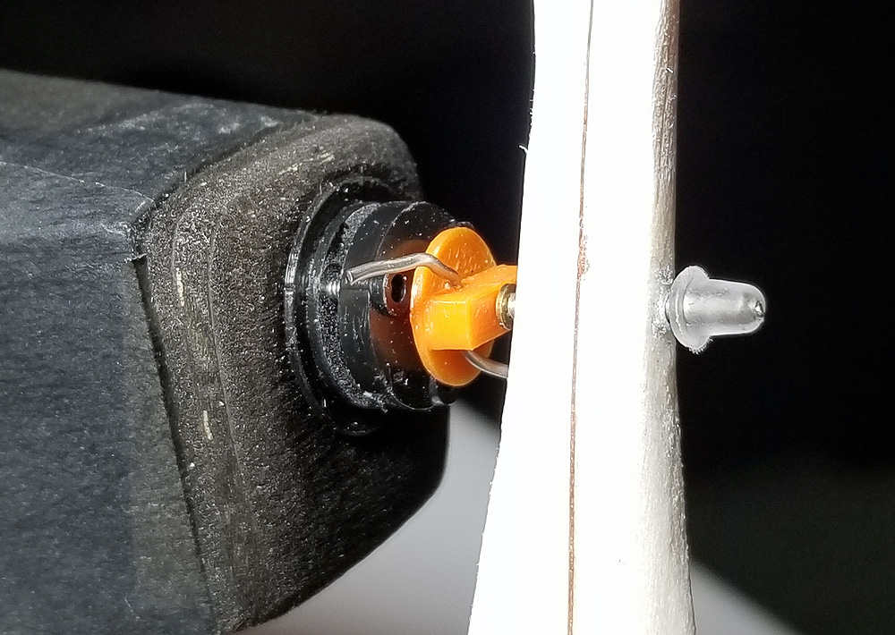
For clutches that sit behind the prop, you need some sort of retainer on the very tip of the prop shaft to keep the prop from falling off. Some people use wire insulation, heat shrink tubing, a crimped metal tube, and whatever they can find. For a few years, I have been using Dubro 0.047 wheel retainers, but there are two problems with them – they are limited in application (0.047″ wire) and … they are no longer made.
Our good modeling friend, Chris Boehm called me last week as he had discovered a solution. Chris tried these silicone items on 0.025″ wire and 0.047″ wire and they might work on larger or smaller wire. Of course, you can also use them as wheel retainers.
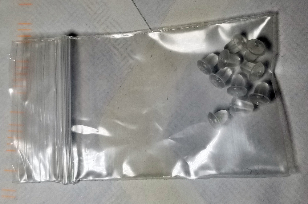
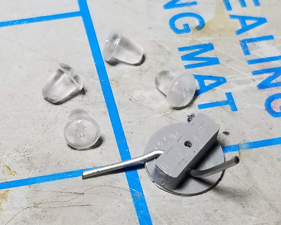
I bought a bunch and now will be offering these separately as well as including them with my VPS Clutches and Boehm Clutches. There will be 4 included with clutches (with no price increase) and you can get a pack of 10 separately for $1.
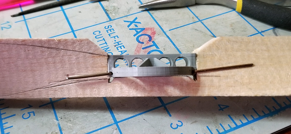
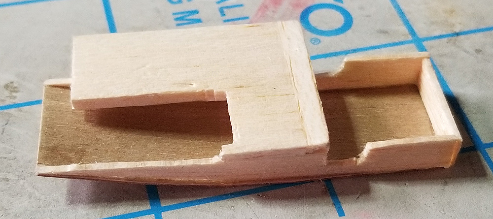
Yes, I just wrote about an electronic DT. But what if you are working on smaller models that cannot support an additional 5 grams? This is a Fuse-Type DT, but I have located the fuse in the rear of the model. With this type, you eliminate the need for routing lines and such. This is not new. You can usually see these on OT Sticks and other larger models. What is semi-new is where the tension to pop the tail resides. It is enclosed within the fuselage for a clean install.
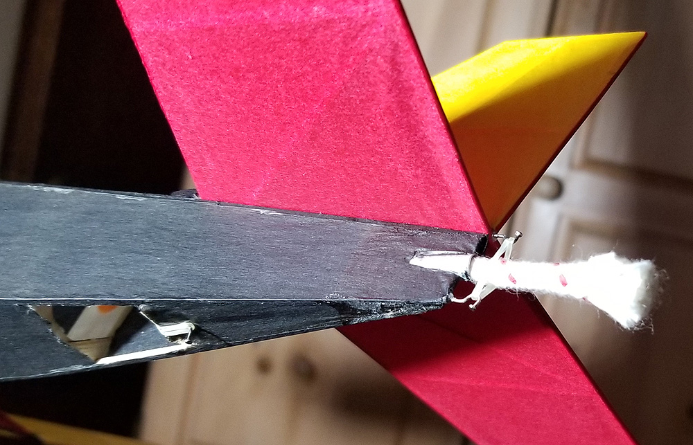
I first saw details of this structure on Al Zimmer’s 1/2-size Gollywock a couple of years ago, but this is the first time I have tried to implement it. It utilizes four pins (or other bent wires) and two dental bands. I hope the weather holds for the weekend and I can get this new Embryo tested. Read the picture captions for more details.
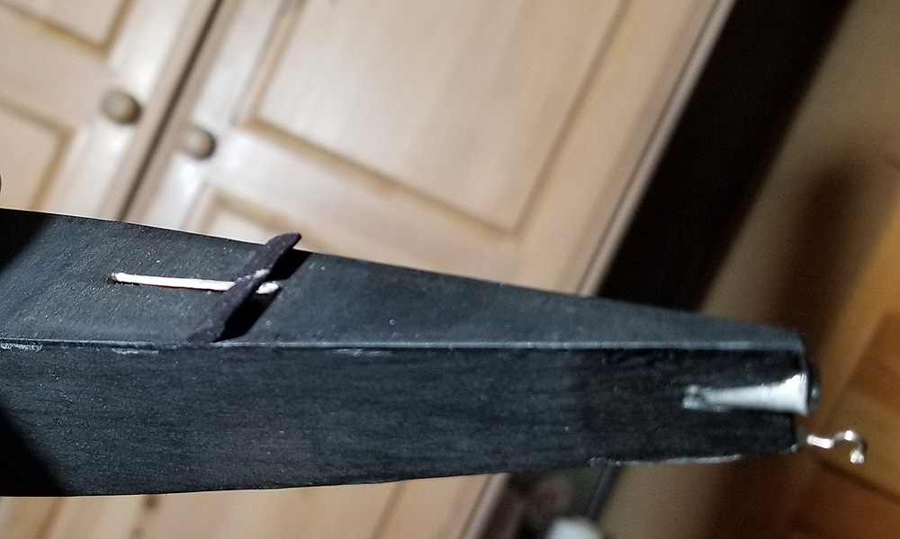
This is the DT setup loaded and ready to go. You can see an anchor point for a dental band at the rear of the fuselage opening. At the extreme rear, there is a pin in the tail assembly and another on the tip of the fuselage. A second dental band keeps the tail locked down until the fuse burns the band.
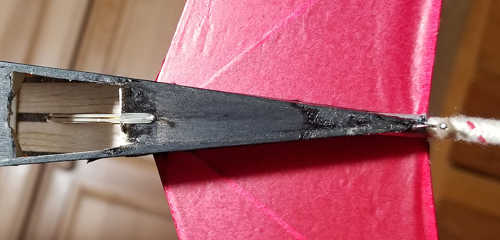
here is a bottom view. You can see the stretched dental band running up to a slot in the top of the fuselage.
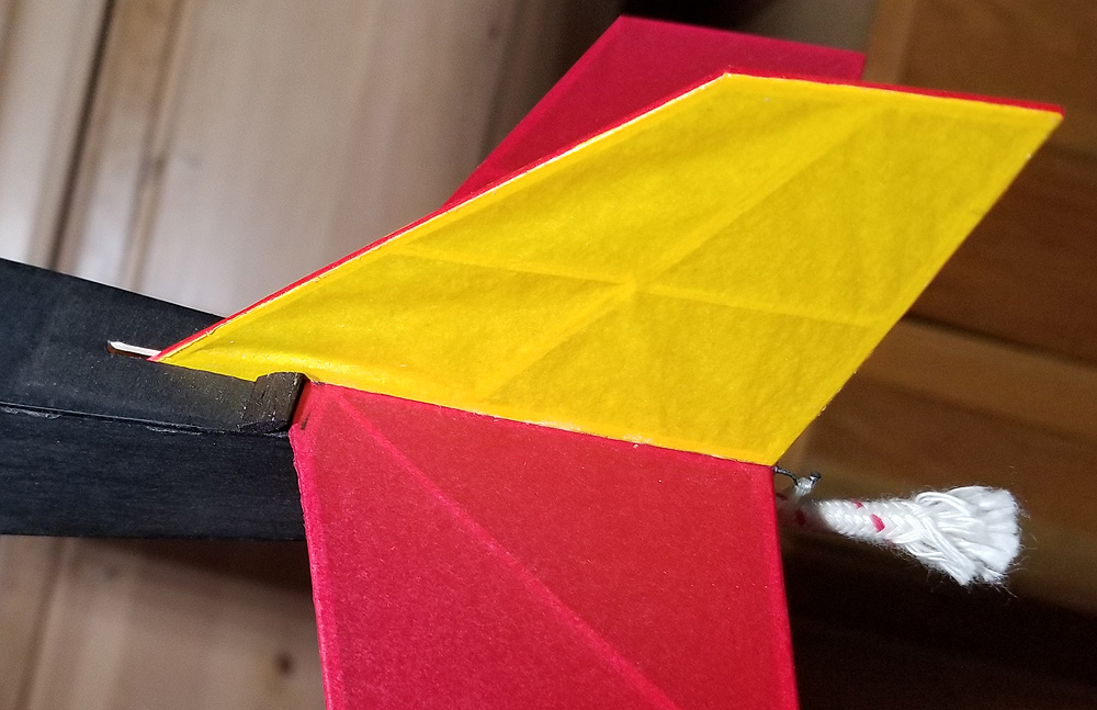
The top view of the tail assembly locked down. At the front, you can see the stop block that positions the tail and the slot with part of the fin in it.
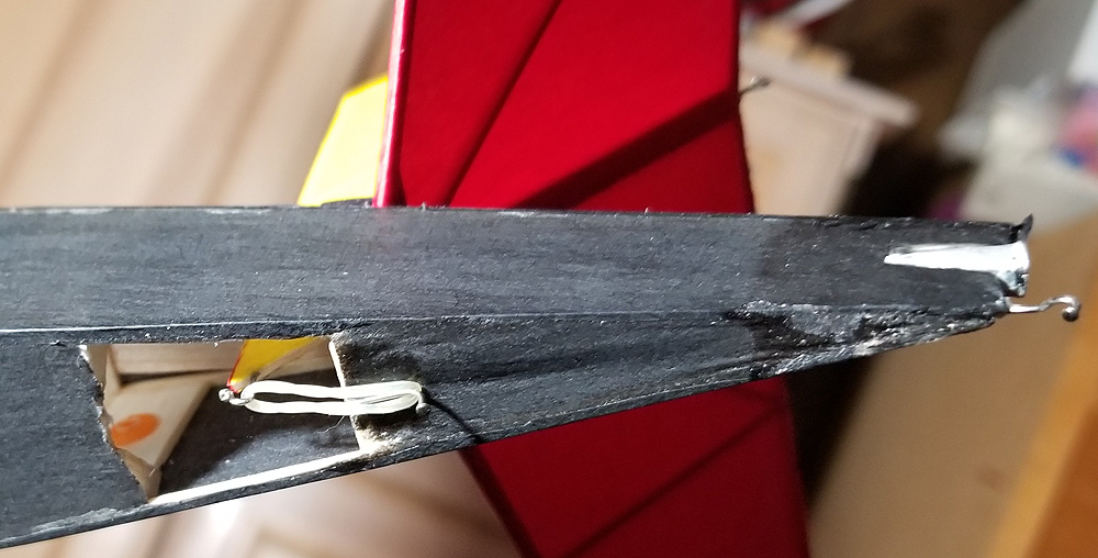
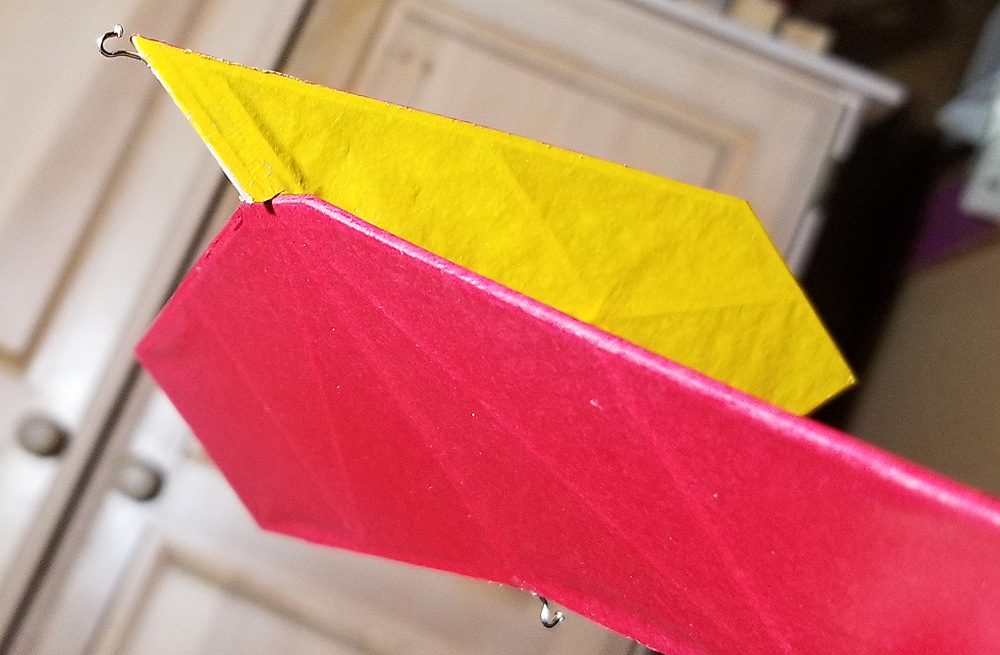
Here the tail is popped up, as if the fuse had burnt through the band.
The bottom view with the tail popped. Now you can see the tip of the fin with another pin hook. This front dental band has pulled the fin down.
Here is the fuselage with the tail assembly removed so you can see the stop blocks and the fin slot.
This is the bottom of the tail assembly. The front of the fin is extended slightly below the surface of the fuselage so that the tail always is within the slot. A pin hook is installed on the tip. The leading edge of the H-stab is straight to engage in the stop blocks and act as a pivot point for the tail assembly.
As spring time has rolled around, I am finally working on some of my outdoor models – yes, I am always behind the curve. This prop is for my Jumbo Scale Aircraft Designs Stallion. You may remember – oops, I guess I never posted the assembly pics for the Stallion…
Anyway, I’ll start from the beginning. Back in the late ’90s, I built my first Jumbo Stallion and I put on a fully carved 3-bladed prop to match the full scale aircraft. It broke just about every landing, but I still have it – here it is:
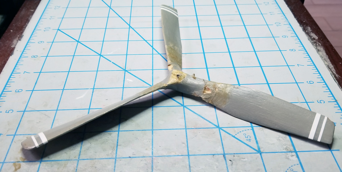
When I built this second Jumbo Stallion last year, I wanted another 3-bladed prop and made it a folder. While it flew the model, I believe it had too little blade area – and – the blades started to pull off the hub. Here is a photo of that prop:
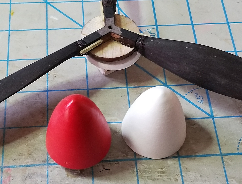
Over the winter, I decided to go with a 2-blade folder of typical design, more suiting to the power loading that I expect for the model. BUT – since I got a 3D printer, I decided the hub would be printed and integrate the base for the spinner. Here are some build pics for this new prop (read the captions for details):
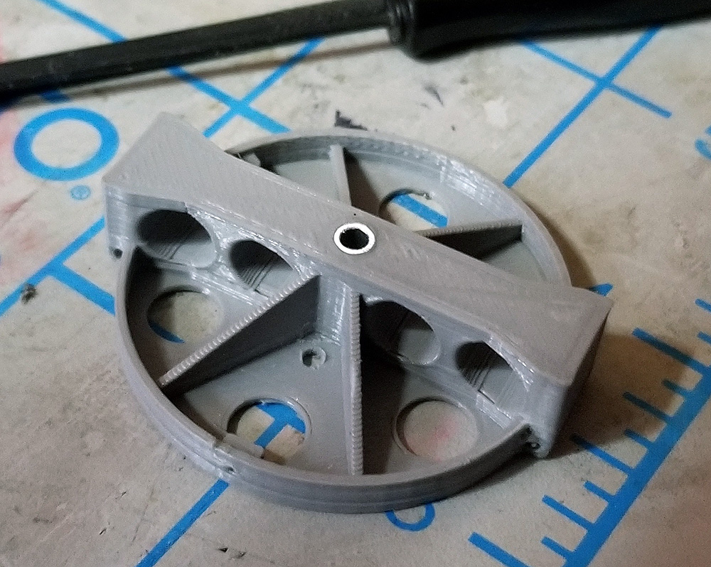
the 3D-printed hub with integrated spinner base. Bushed with a 1/8″ aluminum tube.
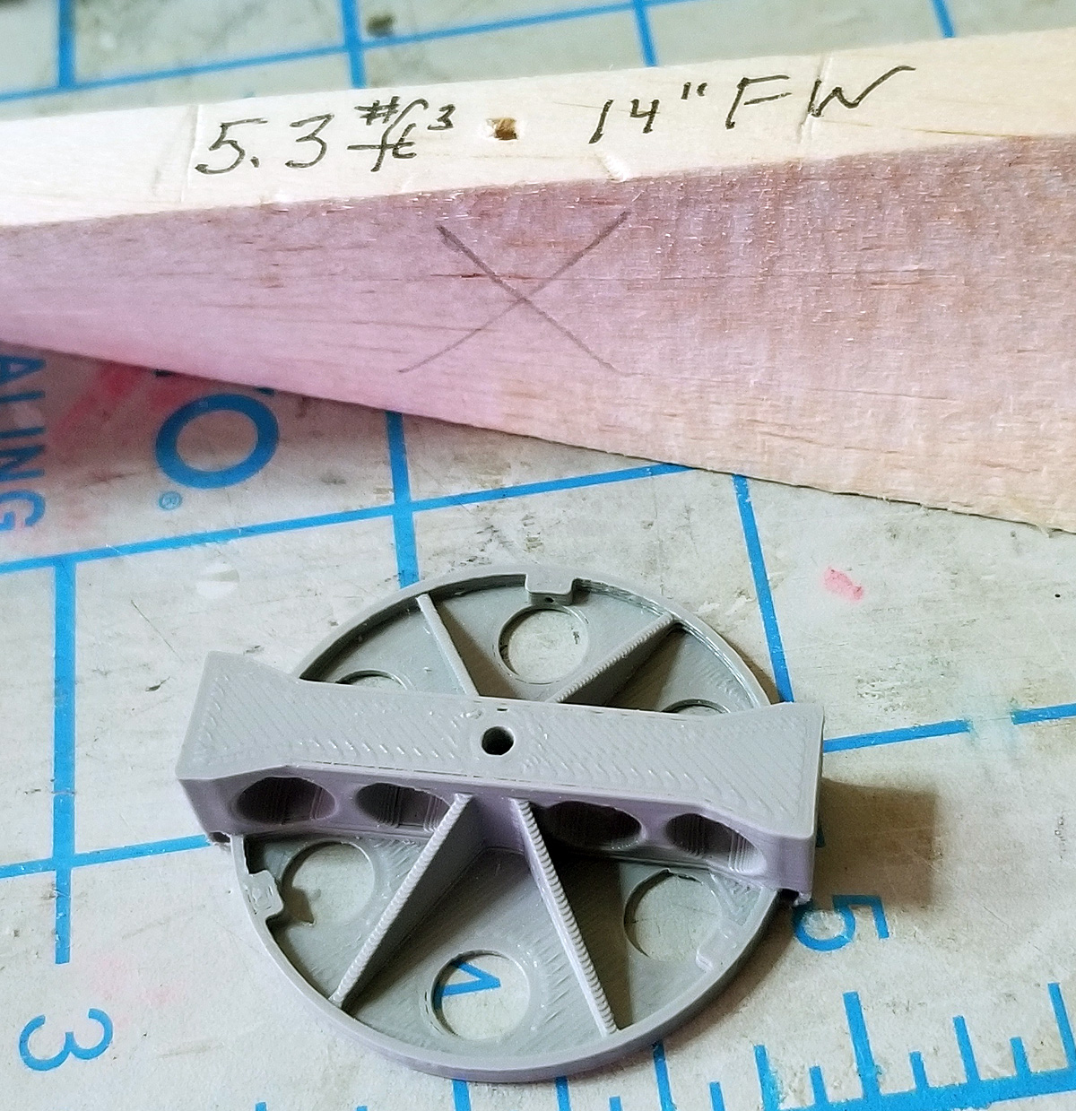
The printed hub and the Superior Props 14″ blank. The final prop is 13″ in diameter. The “X” marks the part of the balsa prop to be removed.
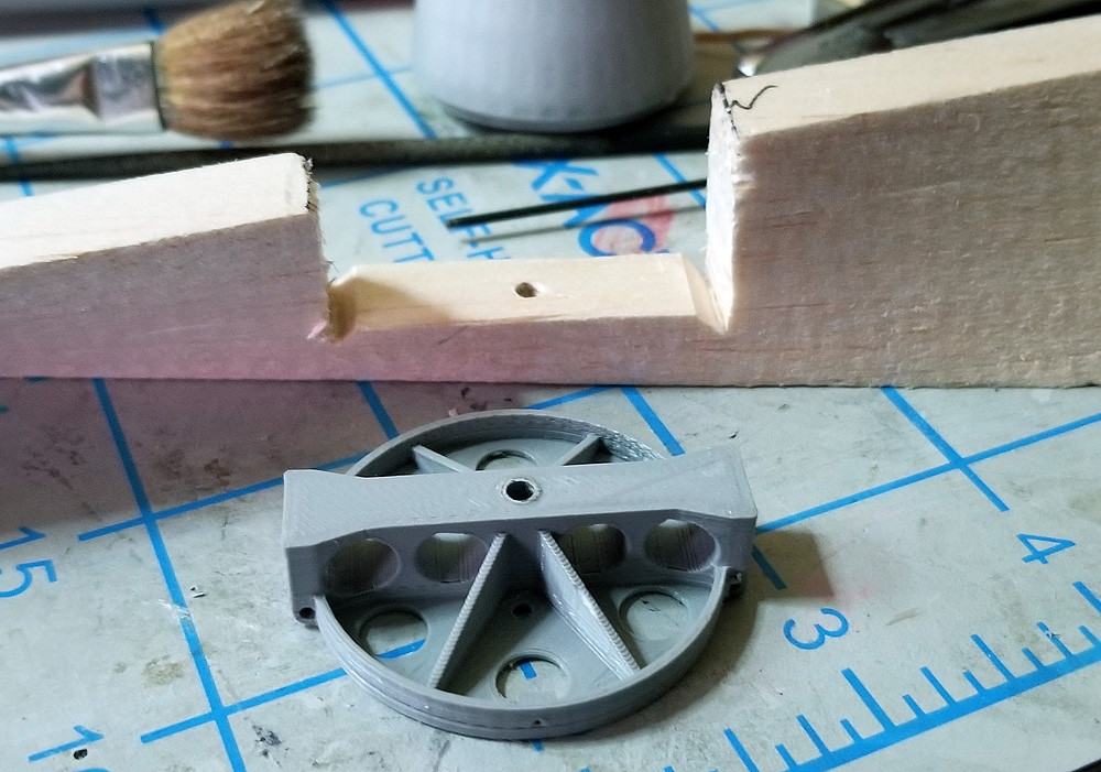
The hub and prop blank – now with the center portion removed. ALL of the center of the prop will eventually be removed, but it needs to be there for construction, keeping the blades in proper relative location.
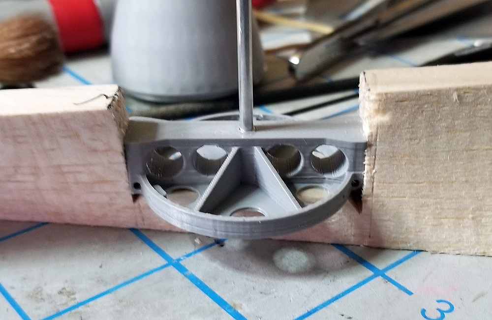
The hub in place with the locating 3/32″ aluminum tubing. The next step is to glue the hub to the balsa – only at the ends of the hub.
Prior to cementing the hub to the balsa, hinge wire had to be installed. Here they are and the basic outline of the prop blades has been marked on the blank.
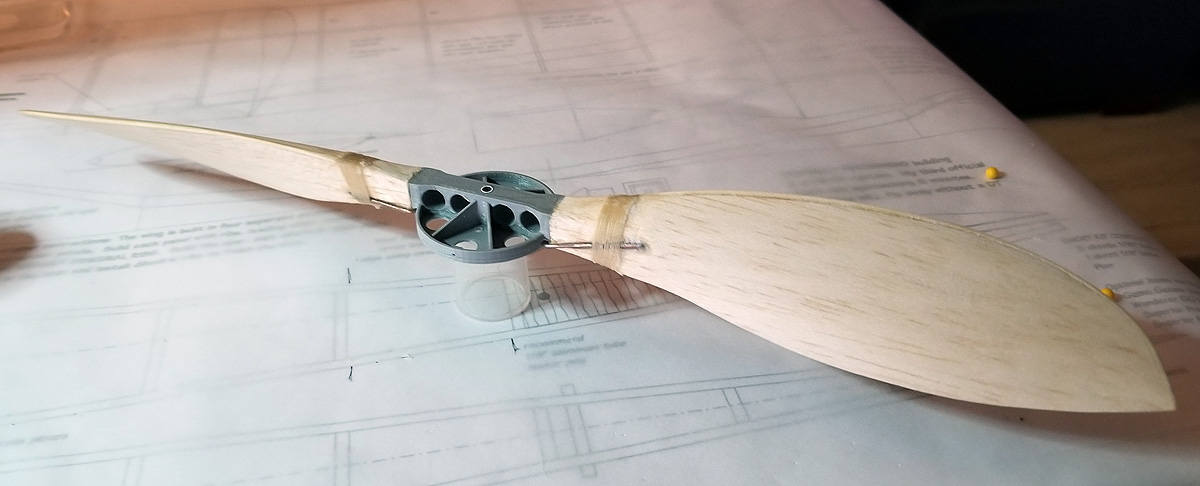
The completed prop. The hinge wires were bound to the blades, bass leading edges glued to the blades, and the blades finish carved and sanded. The blades were rubbed with medium CA, sanded and balanced. At this point, the blades are still cemented to the hub.
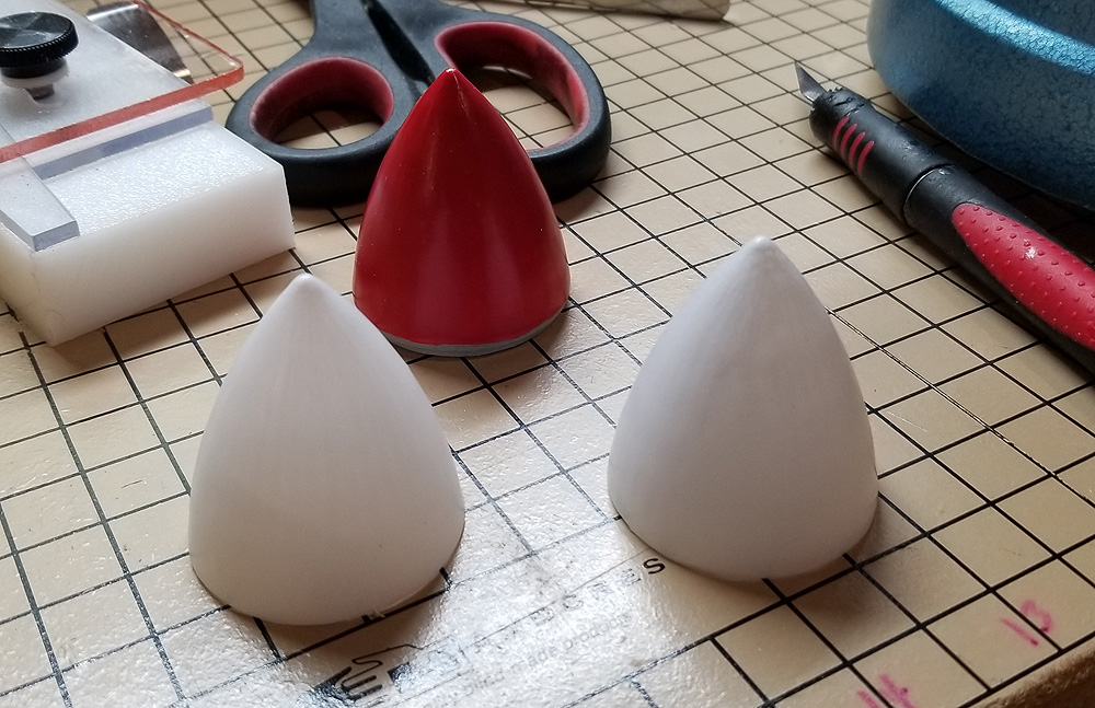
New spinners ere vacu-formed. An accurate plug was printed and sanded (3D printing does NOT leave a smooth surface) and red plastic was formed over it to smooth it all out for final production. Two spinners were pulled from 0.030″ white styrene.
The blades have been painted with Design Master Gray and are still cemented to the hub. Here are the pins embedded in the hub and blades to mount dental bands to hold the prop open. You can also see the three #0 pan-head screws that will hold the spinner to the base. Note that a flange and anchor points had to be printed into the base to accommodate these screws.
The glue joint was cut with a razor saw to complete the folding operation. Full folding alignment is not critical because this folder is always open and only flexes to prevent breakage on landing.
Here is the finished prop mounted on the model fuselage. This prop and hub actually weighed a gram less than the temporary 12″ plastic Chinese prop I used at the end of last season. Testing will happen in two weeks, weather permitting.
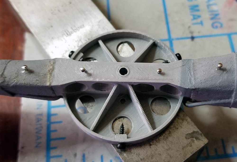
I am finishing up the build of my second Wanderer. No pictures – I’ve been too busy – except here is a shot of the prop assembly.
This is “experimental” because of a couple of parts made from non-traditional materials. I made the noseblock and prop hub from 3D printed plastic. “Why?” you might ask. Well, to see if it could be done, mostly. Below are the details called out in the photo. Note that items #1 and #5 are the 3D printed parts. The other items are just explaining what you see.
Nose Block – Of course, I used the dimensions from my construction drawing to create this. It is mostly hollow, with wall thicknesses of 1/16″. The tip of the nose has a recessed area to receive the front half of a Gizmo Geezer nose button. It seems to be very durable, which was one issue I had with the nose block on my first Wanderer – poor launches and had dives into the ground crushed the soft wood. This shouldn’t crush. However, we all need to remember that if you make the part (any part) strong enough not to break, you are just transferring that energy somewhere else. Also, this has been sanded (mostly) smooth.
Gizmo Geezer Nose Button – Again, this is the front half of the nose button. The back half, the tri-lobed portion with the three small screw holes is omitted and the holes replicated in the printed nose block. The three Gizmo Geezer adjustment screws screw directly into the nose block.
Superior Props Thrust Bearing – a traditional ball bearing thrust bearing to absorb the load and make rotation smoother and less friction-filled.
Superior Props 3/32″ Nose Bearing – So, when I printed the Prop Hub (#5) I printed it with a 3/32″ hole in it (just like we pre-drill the wooden prop hubs). I press-fit a 3/32″ aluminum tubing which is just the right internal diameter to accept the 1/16″ prop shaft. Then, as I often do, I realized that I needed a tube-in-tube to allow the prop to freewheel without the friction generated by the tension of the rubber. I could have just drilled out the plastic slightly to allow the plastic hub to rotate on the 3/32″ aluminum tubing, but I chose to go a different way.I drilled out the hub’s center hole to allow for the insertion of the 3/32″ (Internal Diameter) Nose Button and press fit it into the hub. I used thin CA to secure the aluminum to the plastic. Due to the nature of 3D printing, this disrupted the integrity of the hub – the settings I used in 3D printing allowed for a thin outer wall (about 1/32″ thick) and a 10% cross-hatch fill in all other areas that are not an edge (think of a honeycomb as the interior of that plastic block). So when I drilled the center hole out, I removed the entire wall of the center hole. Using this aluminum hub, I am trying to put some structural integrity back into the part. I couldn’t really print another hub, because the blades were attached long before they were finished and replacing the hub would certainly damage the blades.
Experimental Prop Hub – I made this to see if it would be possible to address some of the issues we have with our current hub/hinge made of wood and aluminum. (At least, I feel there are issues.) When we make folders, we glue blades to a hub, then install a hinge with wires, bond it to the blades, and cut the blades off the hub. The issue I have with all of this – and maybe some of you have seen this – is that the aluminum hinge can get twisted. This creates two problems: a) the blades do not lay back uniformly and b) when this happens, the pitch of the blade can change.I designed this hub with the holes for the wires integrated into the hub. They cannot move or twist like the aluminum hinges. It took a bit of experimenting to get the holes properly located, but I think they are right. As mentioned above, I have already encountered some things that need to change IF we choose to replace the wood/aluminum hub with this plastic one. I will fly this prop and see how durable the hub is. At the current print density, it is no heavier than the wood prop, so we aren’t sacrificing weight – durability is the test for this flying season.
Folder Blades – Here you can see the hinge wire, where it enters and exits the hub, and how it is bound to the blade. This is typical of our current hinges, but, as stated above, the hinge is now integrated into the hub, rather than being a separate piece that requires binding and bonding to the hub.
Dental Band and Pins – these are required for Flying Aces Club rules. The FAC does not permit props that fold prior to landing, so folders must be help open during flight. You might ask “so why put a folder on an FAC plane?” – well, a folder will flex on landing, absorbing that shock of landing. Remember above where I said the nose block was strong and we transfer that energy to other parts of the plane? Here we are trying to absorb that energy of landing and hoping to prevent a) breaking of the prop on landing and b) breaking of the fuselage nose when the nose block pops out. This works well, trust me.
Tube-in-Tube – You can barely see the 3/32″ internal aluminum tube. You can just see a little bit sticking up above the hub. THIS IS CRITICAL. If you make the internal tube the same length as the external tube (in this case the external tube is the #4 aluminum nose bearing), the prop will not be able to freewheel without binding, due to the tension of the rubber (braided motor) pulling back on the prop shaft. This pull will pull the clutch back on the internal and external tubes equally and prevent free rotation. By making the internal tube longer than the external, all of that binding and tension applies to the internal tube only and the external tube (and prop) are free to spin. I often forget this and wonder why my prop locks in glide.
Superior Props Freewheel Clutch – This clutch its in front of the prop and firmly attached to the prop shaft. In the position shown here, the bail (wires coming out if the side of the aluminum clutch) are engaged in #10, the drive pin. This is a fairly positive clutch as centrifugal force spins the bail out when the rubber motor is driving the prop. when the power is off, the shaft stops spinning and the clutch stands still. The prop freewheels and when the drive pin comes around, it hits the back of the bail and flips it forward. The legs of the bail are long enough to engage the pin under power, but short enough to clear the pin when folded against the clutch. A notch needs to be ground int eh prop shaft to accept the set screw or the force of the wound motor could pull the shaft out of the clutch if you just rely on the friction of the screw on the shaft.
Drive Pin – this is part of the clutch and it is a pin embedded in the prop. This pin is 0.039″ wire. I used 0.032″ (1/32″) wire on my first Wanderer and the pin bent. I think that 0.032″ wire was just too weak for the forces applied during full winds, so I went up to the next size of wire. It is possible that I should have gone up to 0.047″, but we will see. Given the internal structure of the plastic hub (mentioned above in #4), I chose to drill all the way through the hub and the drive pin wire has a short “L” bent into the back side. This “L” is positioned right up against the flange of the #4 Nose Bearing and CA’d firmly. This should be strong enough.
Prop Shaft – This is just a typical 1/16″ music wire prop shaft. Nothing special here, other than I choose 1/16″ because I am 100% positive that 0.047″ would be too weak for this size of plane. I used 1/16″ on my first Wanderer and did have a couple of bad landings where the shaft bent slightly.
This entire assembly is not light. It weighs 18.7 grams as shown. This plastic nose block weighs 5 grams and the finished prop before all of the hubs, bearings, pins, etc was 10.4 grams. So all of the accessories (aluminum, tube, nose bearing, thrust bearing, clutch, drive pin, pins, dental bands, and prop shaft) add the additional 3.5 grams. The same assembly on Wanderer #1 weighs 16.6 grams. Most of the difference is certainly in the plastic nose block. This 2-gram difference in not objectionable to me (yet) and maybe I can move the wing forward a little and make better use of the longer tail moment. That is yet to be seen.
Imagine a world where you’ve been flying Free Flight for years and years and, while you have had the occasional lost model, your efforts and skills do not require you to be overly concerned with flights over two minutes or fly-aways. Such was my life until about 4 or 5 years ago.
Then something happened – I started losing models with much more regularity. My planes were flying better and longer and were catching more thermals. I decided to try my hand at the Dark Art of Dethermalization. I’ve tried pop-up tails, pop-up wings, pop-off wings, and even swinging weight DTs. And while building the DT mechanism requires planning and careful adjustment to ensure there is so little friction that the mechanism works, a bigger challenge (for me) has been “How to Activate the DT”.
In my own personal trek, I am comfortable with burning fuse DTs. And when I say “comfortable”, I mean they are pretty easy to install, they are light-weight, and they work reliably (say 85% of the time?) If they don’t work, it is usually because the fuse was not fully lit or that it was damp and would not hold the burn. One problem for me has been an understanding of how long to make the fuse. Hence, most of my flying buddies will know that when I set a DT for a 2-minute flight, it might be 3 minutes or more before the DT pops. But I use them most often.
I have tried and tried (bench-tested) viscous DTs. I even make and sell one. But – and take this for what you will, even as a potential customer – I don’t trust them. I have never felt that 85% comfort that a burning fuse gives me. Try as I might, I cannot figure out how to set them to run for 2 minutes AND release the line. They always either go too fast to start (but still have power to release at the end) or they do run for two minutes (but have no remaining power to trip the release at the end. So, I do not use viscous DTs.
I have tried mechanical clock-work DTs (Tomy Timers), both homemade and commercial products. They do work and I think they are reliable. But again, – for me – it is a guess as to how long the countdown to release is. While the mechanics are governed and the shaft rotates at a set rate, I am often left wondering if I have twisted in 3 revolutions or 4 – or how many. In addition, they are heavier – 3-5 grams or more.
Now I have decided to try something new (to me) and very repeatable – an electronic timer with a band burner.
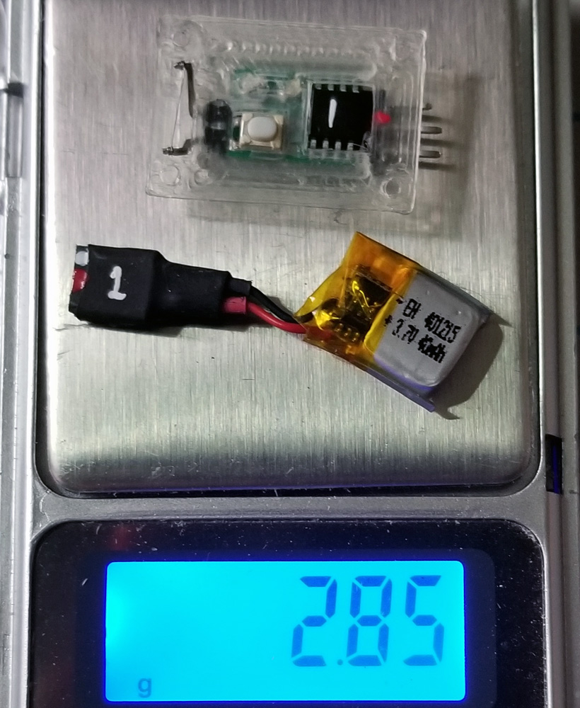
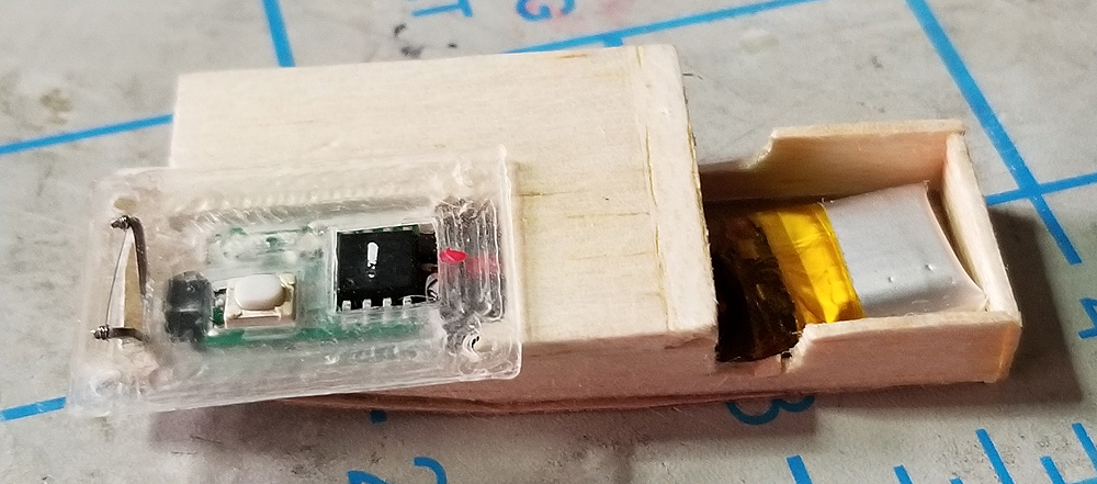
This is a small, single-action electronic DT, developed by Liav Hershkoviz and licensed to Bernard Guest of Hummingbird Model Products. With the connectors provided (they could be smaller) and the 3D-printed mounting shell, these come in at just under 3 grams all-up weight. (link at the bottom of the article)
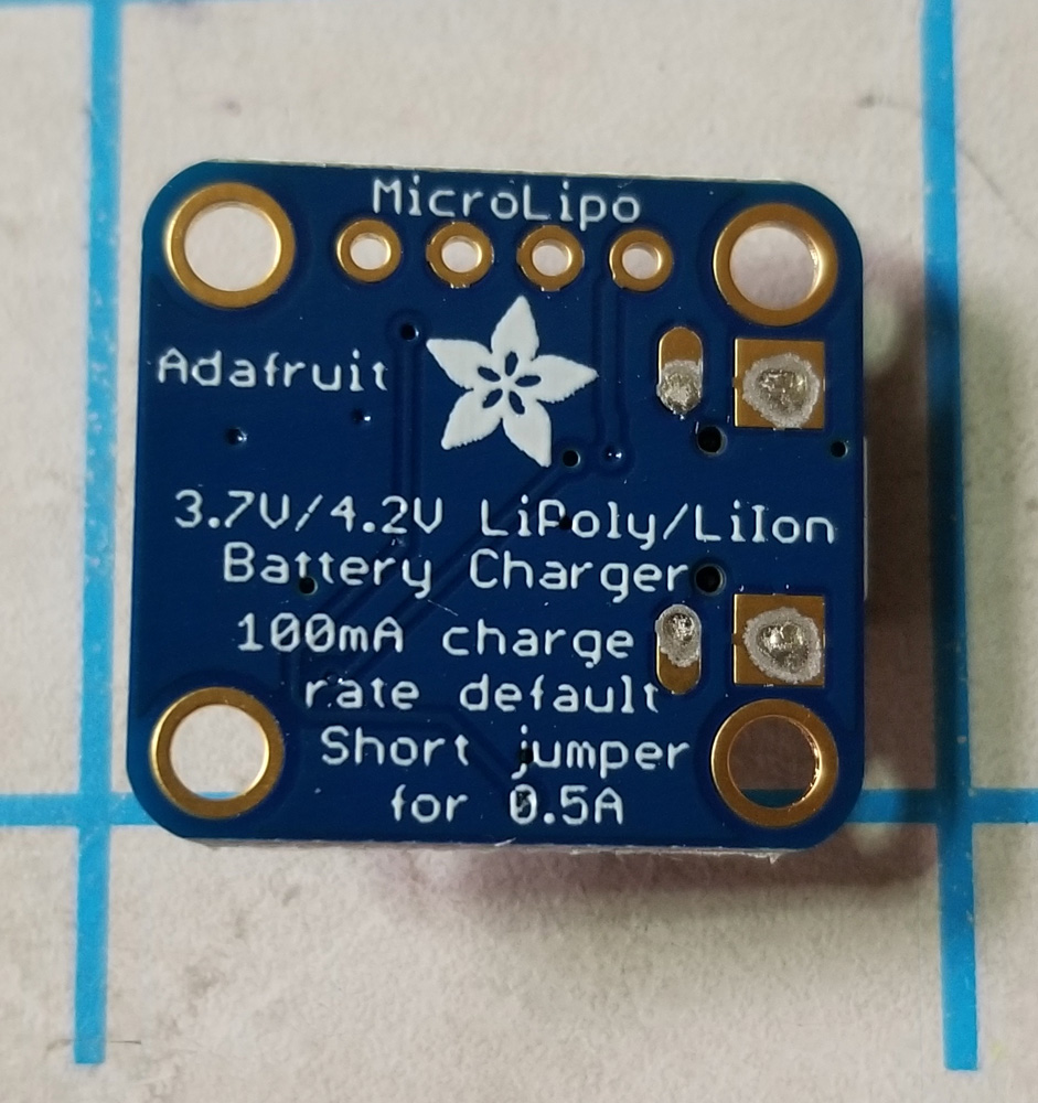
I’ve decided to try these on my endurance models (where I am likely to encounter flights over 2 minutes. However, before I mounted this in a model, I knew that I needed to come up with a charger for the tiny, single-cell LiPo 40mAh battery. Bernard helped me find one that would not pump out too much power and ruin my little cells. I found the AdaFruit 1904 mini-charger (link at the bottom of the article).
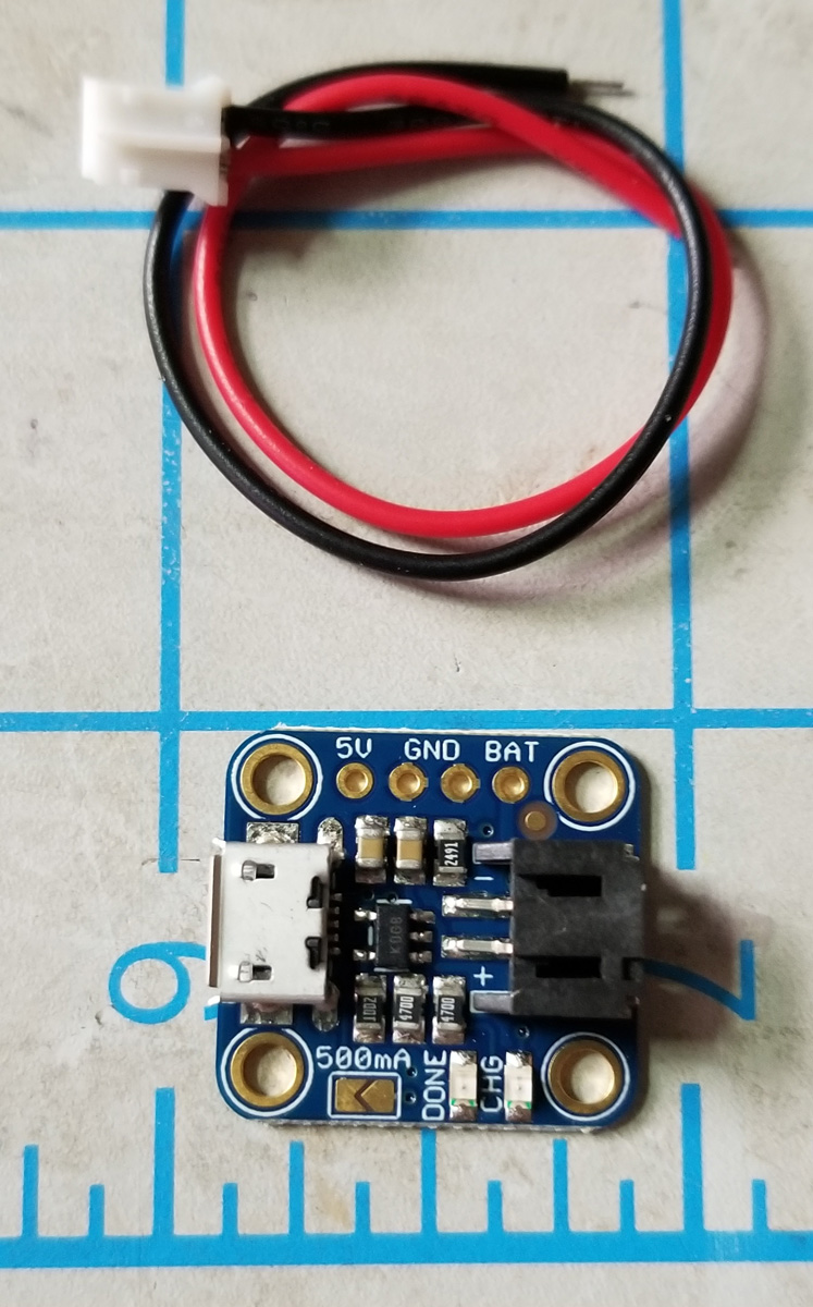
It comes as shown above, the small wire is the output. You will need to hook up a plug to match the pins on the battery. The connectors you choose are really up to you, but if you buy the batteries from Bernard, they come with a “standard Futaba servo plug”.
One of the nice things about this charger is that it runs on USB power and the power input is from a USB-Micro plug. This matches my plans exactly – because I wanted USB power so that I can just use a phone-charger-battery at the flying field, if I need to recharge these tiny batteries.
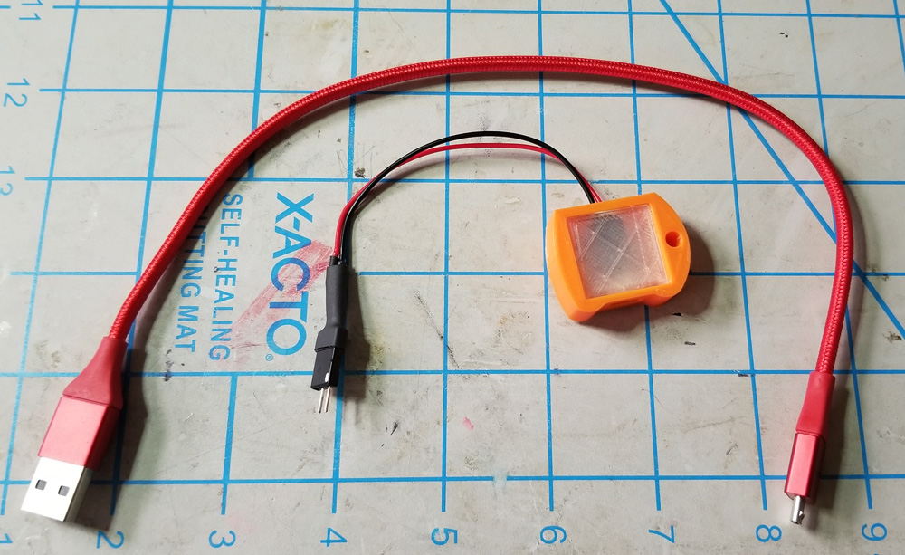
But, this tiny board is open to the elements. While I don’t plan on using this in the rain, I want something that will protect the board from abuse and short circuits. I found that someone has designed a 3D-printed case on Thingiverse (link at the bottom of the article). I downloaded the files and printed out a case. I bought some “clear” filament, too, so that the charger LEDs can be seen through the case.
I decided to do my first install as a retro-fit into my Jimmie Allen Sky Raider (I had a home-made clockwork timer in there). I removed the old timer and installed this one. I built up a support for the board and then a cover for inside so that the board and battery were protected from the rubber beating on them.
After programming the timer (video link at the bottom of the article), I confirmed the operation. I even made a video so that you could see how this operates. Here I have it set for 15 seconds, but will probably go with 2:15 for my flights. Once the time is programmed in, you just need to turn on the timer and activate it. It will always kick at that time. Here is the demo video:
It been just jam-packed around here. Spring has finally come, although we are still trying to shake loose old man Winter (snow last Sunday). I’ve been feverishly packing orders for all of you (all that have ordered). I took a trip over the weekend to the Prop Factory and talked to my parents – and brothers. I am heading south again this weekend. It just seems I cannot catch up!
Spring is definitely here. Daffodils have popped out locally. Wildlife is appearing – turkeys, deer, and Sandhill Cranes have been seen in the back yard, not to mention all sorts of songbirds, chipmunks, and squirrels. I love watching Mother Nature, especially those big birds.
Today, I took a little time and repaired three indoor planes before out last local indoor contest of the season coming up this Thursday. I replaced a missing strut and patched a tissue hole on the BAT Monoplane. I replaced a missing strut on the Stout 2-AT, but more importantly, replaced a section of broken leading edge and patched the tissue on that bay. And my Turbo Cessna 195 suffered several LE and TE cracks – I hope it still flies.
After that, I took a flying break. It is warm and calm enough outside that I took out some old Jet Cats. I had built a super light (for me) T-37 Tweet that never flew up to expectations – well, never flew well at all. It won’t fly ever again after today as I snapped off the tail – again – on a nose-in landing.
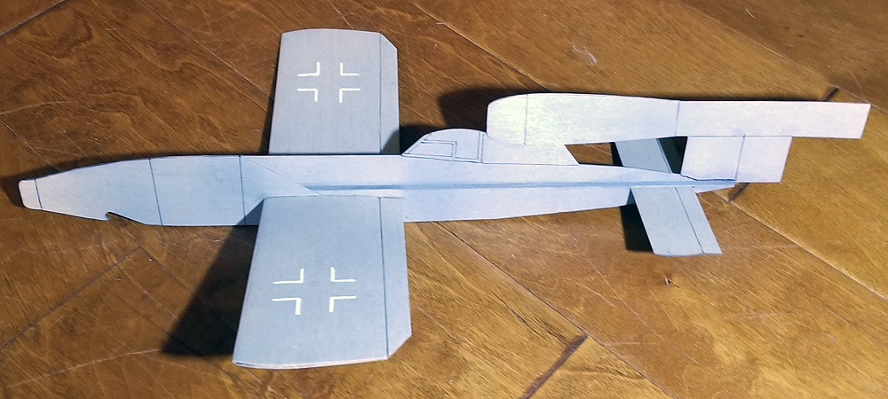
I took that back inside and grabbed another that had been relegated to shelf-sitting – my Fieseler Fi-103. I built this a year and a half ago as an indoor model. It has always been tricky, but it managed to win its first contest back in 2017 and I have always believed the design has potential (if not this model).
The fuselage was warped with severe bend right at the leading edge – the result of a few too many hard nose landings. In case you don’t know, there is a tremendous amount of snapping force to the side on some of these landings. As I said, the Tweet’s tail snapped off and this one had a big crack in the front. I squirted some thin CA on it and held it straight and went outside.
right after building in Oct 2017
Jet Cats are a mystery to me. But I persist. This one – as all of mine usually do – required a bit of tweaking. But by removing a touch of clay off the nose and adjusting my launch, I was starting to get some really good flights in my tight back yard. Unfortunately, the launch would be a nice right-handed climb into a transition to….straight away, with little turn. All this is on one loop of 1/8″ – half the rubber I would use in a larger space.
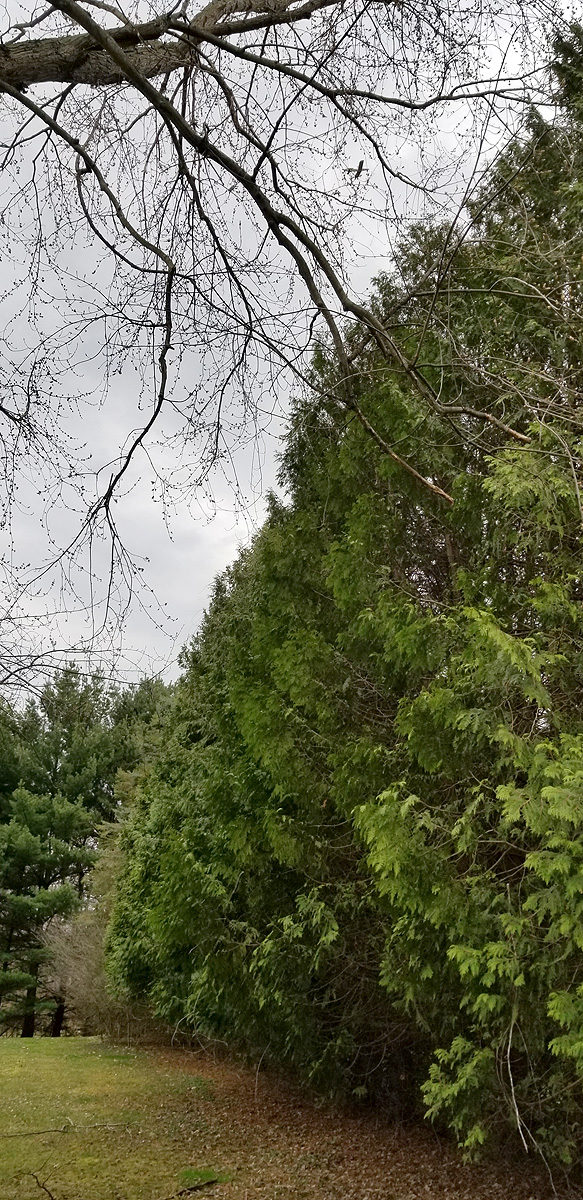
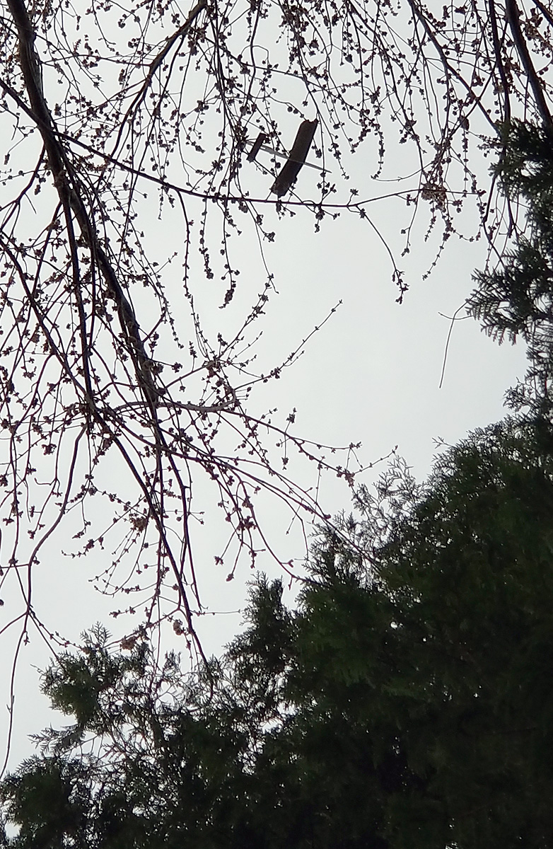
I took of about half the clay on the right wing tip, hoping to allow a left turn and walked upwind (up-breeze?) and launched. The thing did its very pretty arcing power flight and settled into cruise about 50 feet up. There was a little left turn, but not much. But it did come around and headed for the row of arbor vitae that lines the back yard on the north side. I know it was about 50 feet because that is the estimated height of these trees – and it flew over them. I saw and heard it hit the huge old maple tree between the arbor vitae and the house.
I walked around and found my plane – parked as pretty as you please way up in that maple. I looked at it for quite awhile as it is up higher than I can do much about. I even got out my 35′ pole and lifted it as high as I could and was at least 8 feet short. It is resting on two small branches at the nose and tail and pointing into what little breeze there is.
I am sure it will fall out sooner or later – but will that be before or after the rain comes?
It’s that time of year again! April 1st starts our 8th Year. Take advantage of a 10% Discount on ALL products on the web site by using this code during checkout: 8thYEAR (copy and paste for best results). The discount is good until 15 April 2019.
In addition, here is another New Product!
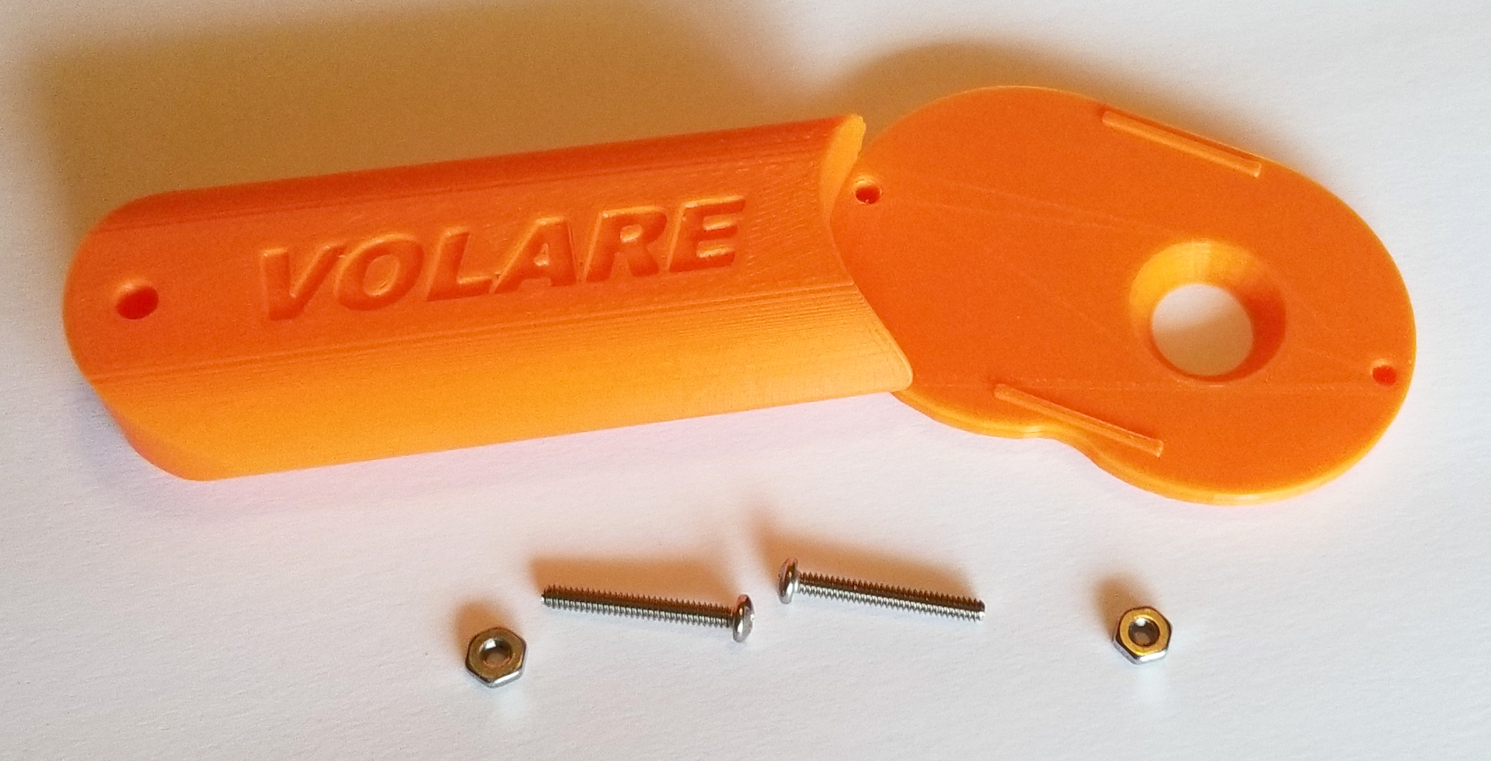
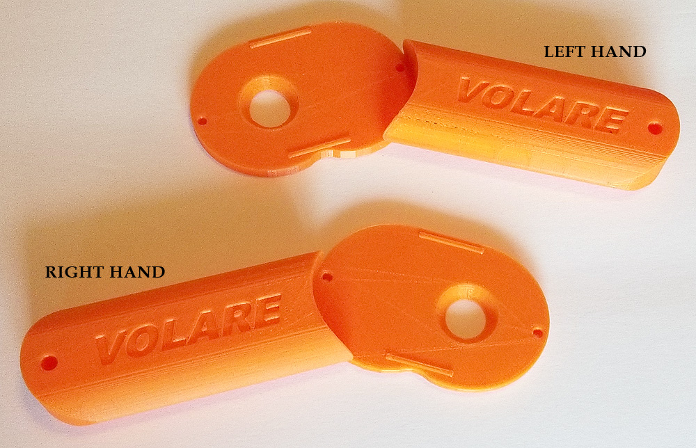
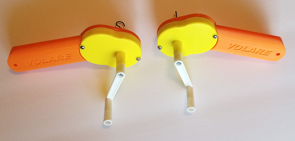
My latest 3D Printed Product – a handle for the K&P small winders. Comes in Right or Left configuration. Buy a winder at the same time and I will refund $2! Comes with two screws and nuts.
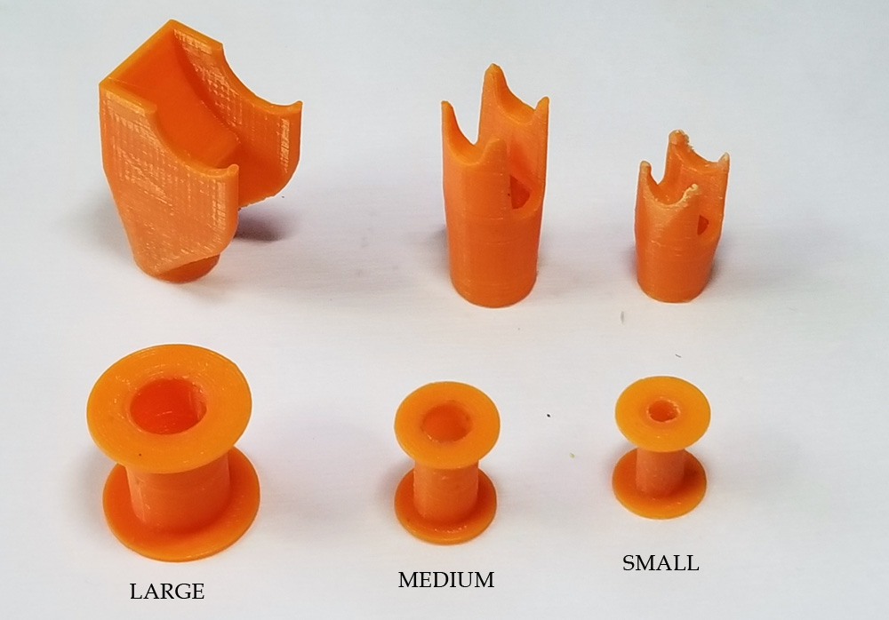
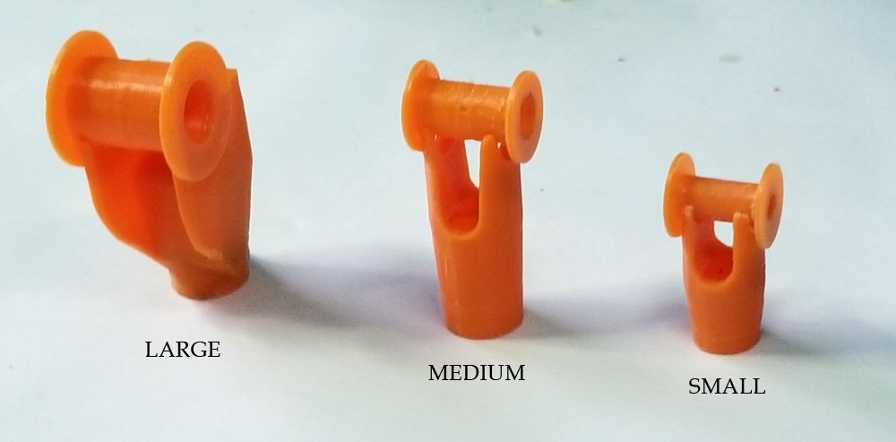
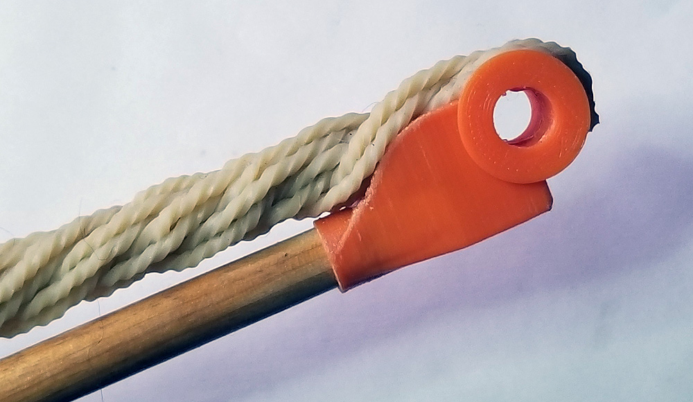
It never ends here in rural Michigan. I’ve finished up the Falcon Special II Short Kit and have a full range of 3D Printed Stuffer Stick Ends and matching Bobbins. Stuffer Ends are sold as singles; the Bobbins are sold in pairs. Or buy the Combo (1 Stuffer End and a pair of Bobbins) for a reduced price!
All short kits and 3D Printed items are small batch – made on demand.
The weather seems to have broken and Spring is here (we hope!). Soon it will be Outdoor Season again!
Today seemed like work, work, work – with no stopping. I packed orders and got them out the door, but that is nothing new. Today, I…
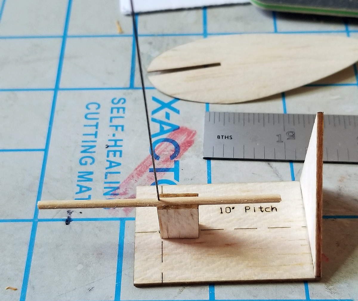
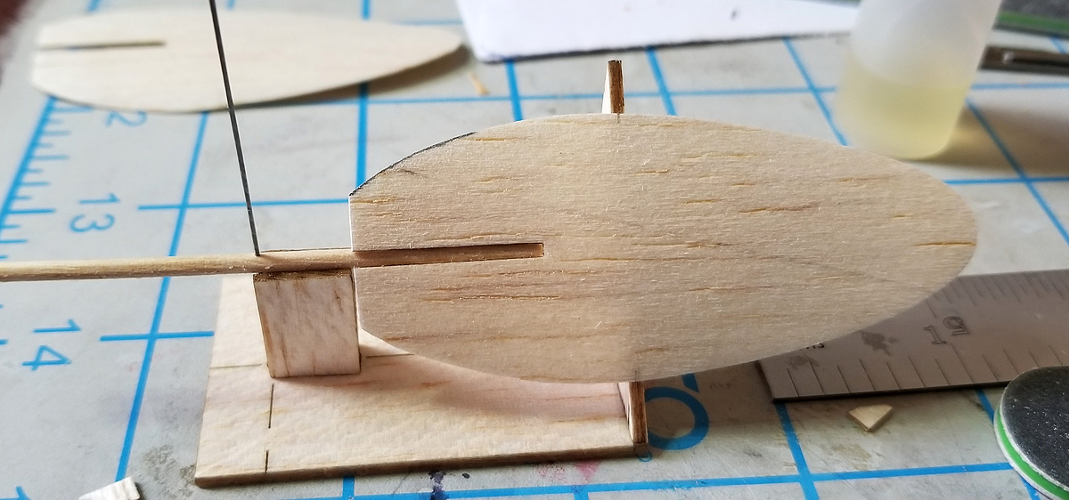
designed and laser-cut and built a formed blade pitch jig
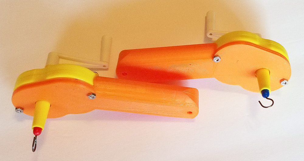
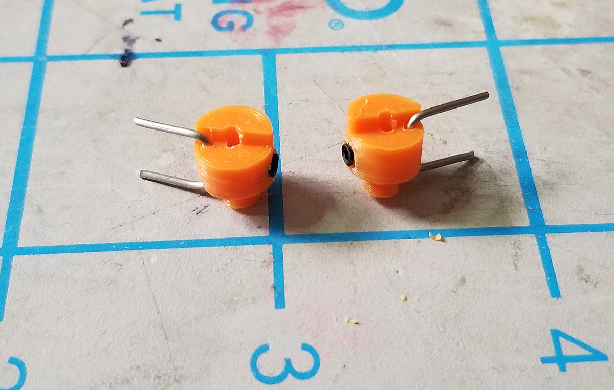
designed and 3D printed clutches for reverse operating props (several iterations)
finished up a replacement WWII NoCal
designed and 3D printed a test nose block for a Wanderer
Here are some details
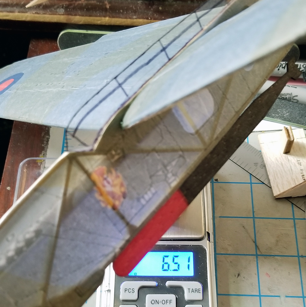
1. for my new Fairey Barracuda NoCal, I built a formed prop at 6.5″ diameter and 10″ Pitch. I drew up parts for a fixture to set the blades at 10″ Pitch
2. A customer wanted clutches for a pair of counter-rotating props. Our Superior Props Clutches are machined out of aluminum and only work for “normal” rotation. It would take quite a bit to make one for reverse operation. I had experimented with 3D printing a clutch and had some relative luck, so I thought I would try to create a pair. On my fourth design, I feel I have conquered the issue and have a workable pair:
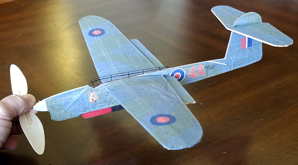
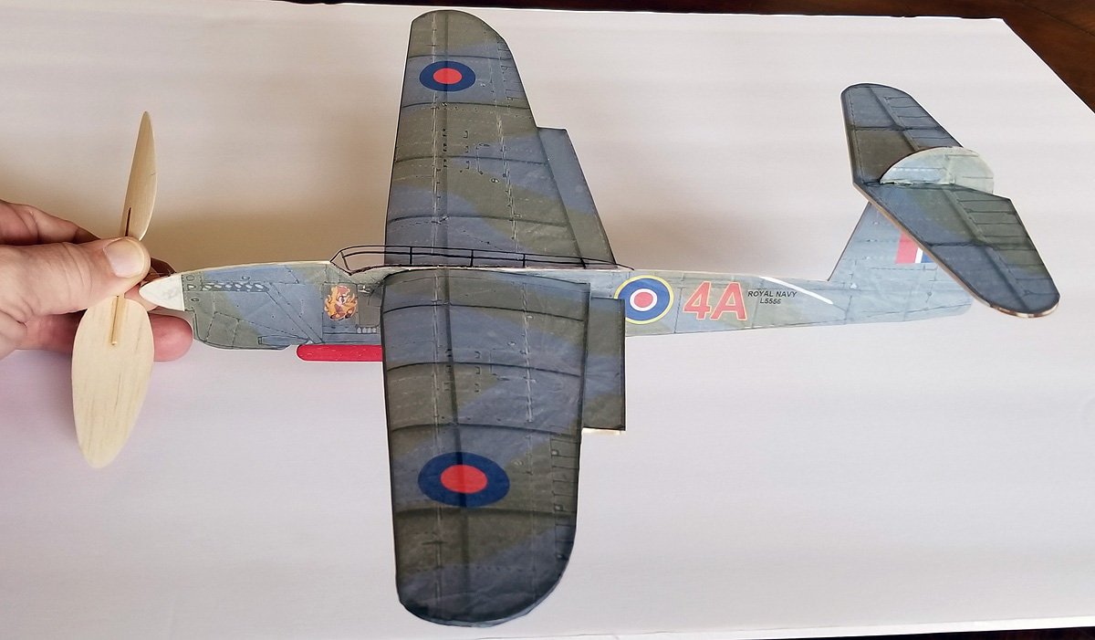
3: Last Thursday, I lost my great-flying Fairey Barracuda NoCal – it got stuck in the rafters at the flying site and will likely never be retrieved. So I built another one over the last couple of days. Notice the color differences between the old model and the new. I discussed coloring when I talked about rebuilding my Peanut Barracuda. The old colors were sampled off a 3-view. The new colors are actual RGB equivalents to Fleet Air Arm colorings. These values can be found online. So the NEW colors are “right” – in fact, while covering, I remarked to myself that they reminded me of color photos of Spitfires from WWII.
the last photo of my old Barracuda – taken in February
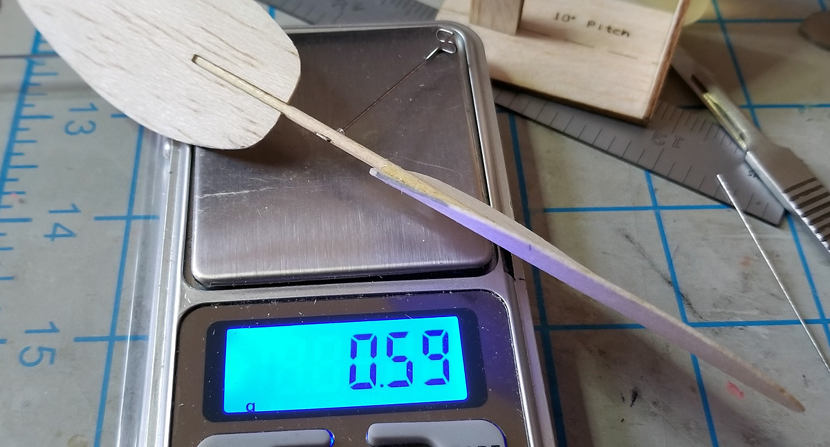
finished weight of the new one (unbalanced) – rules require a minimum of 6.2 grams.
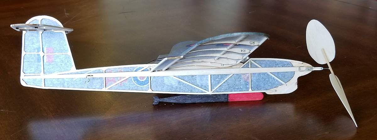
backside structure – including laser-cut parts and tapered motor stick.
the colors are hard to show
here it is on white
4. I am mentally preparing to rebuild my Wanderer or build a new one. One of the problems I had with the old one was the balsa nose block – the Gizmo Geezer thrust button smashed the balsa on several hard landings. I wondered if I could print one. Well, I could – I designed and printed one today. In order to prevent redundancy, I reproduced the “bottom” part of the GG nose button into the nose block. We’ll see if I can use it.