Photos and video below.
This model has been on my “to-do” list for many years. Tom Groening was a Cloudbuster who is no longer with us. He flew locally without going to regional or national competitions. I remember flying with him when our outdoor contests were held at Broome Park in Flint, MI. This was before my “break” in modeling. I also remember Tom flying this Embryo – I seem to remember green and black colors. Tom was a quiet, bespectacled man with curly hair. Tom was also murdered in a home invasion in 2003. So this is a tribute to Tom. By the way, this model never had a real name, so I dubbed it “Dragonfly”.
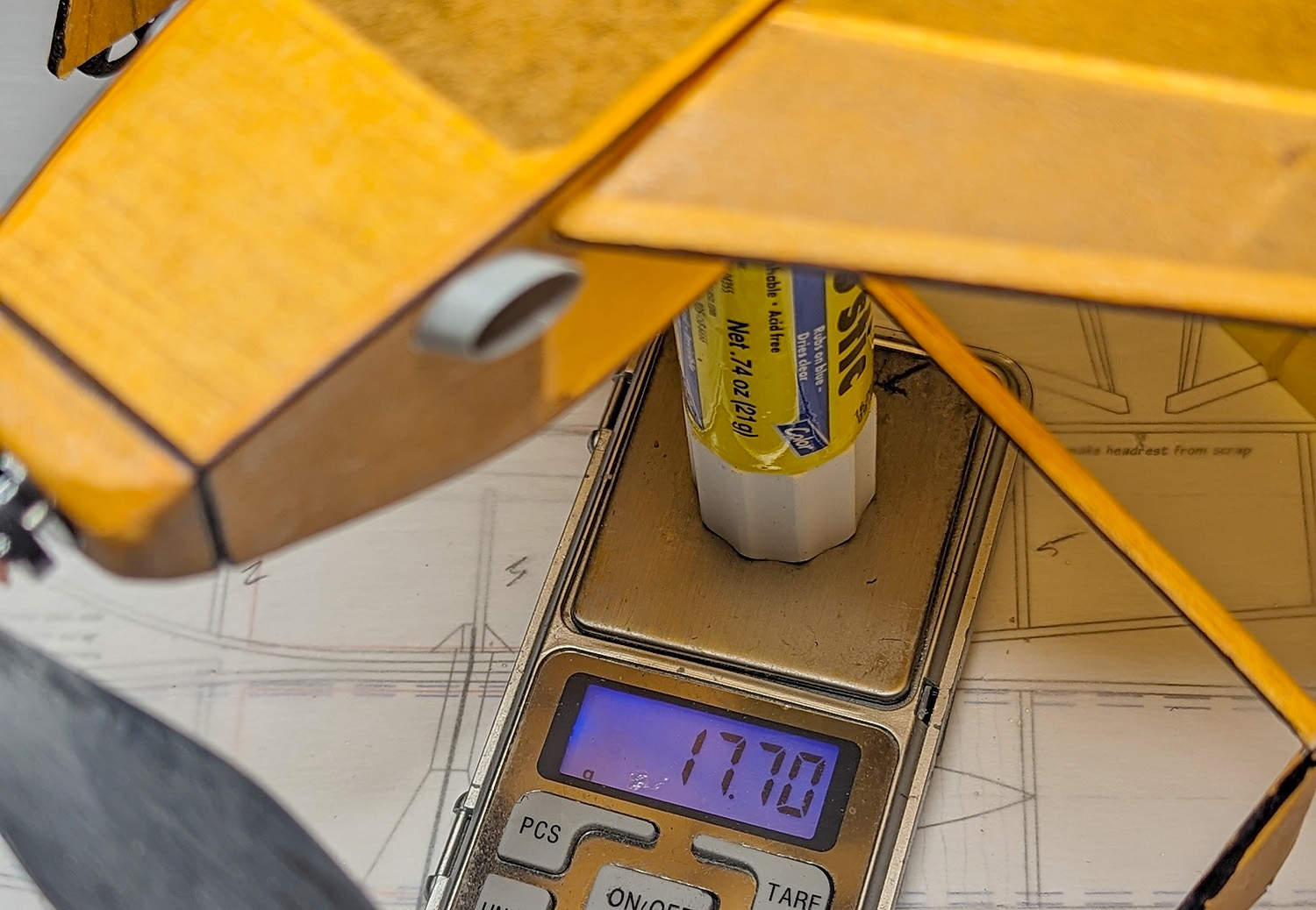
This model is full of idiosyncrasies and oddities and redrawing the plan presented almost as many challenges as building it. The plan originally appeared in the Cloudbusters’ Newsletter at least 20 years ago – maybe more – probably while Tom was still alive. Actually, drawing is easier and helped me define how to build the model for the next guy (you?). One of the first things I had to do was make sure the fuselage was large enough to contain the required 3″x1.5″x1.25″ box. It seems that the maximum dimensions of the fuselage met the requirements – but the fuselage has a top-to-bottom taper – and the bottom didn’t meet the dimensional requirements. That is about the only change I made to the model, excepting some changes made to help the builder align the parts. Here is a list of things to be aware of when building:
FUSELAGE SHAPE
As mentioned, the fuselage is tapered top to bottom. This creates a challenge when building. I found that it was easiest to build the sides (per usual) and then build the 3D fuselage over the top view, but build it upside-down. This works for two reasons: 1) the top side has a long flat surface and 2) the top is widest and you can shim the sides in from this top base to create the narrower bottom. As I thought about this before I even built one side, I decided to laser-cut all of the cross pieces as they are all different. It is too bad that I didn’t think of this before Winn Moore built the first prototype – he had to measure and cut all of those cross pieces and struggle with the build. For the next guy, he will just have to find the proper piece on the sheet and install it on the build.
This taper also caused some calculations (where redrawing the plan helped) when it came to wing installation. The root rib angle had to be re-calculated since the side of the fuselage where the wing mounts is NOT vertical and has some additional degrees of angle added to it. Use the provided Root Rib Dihedral Gauge to set the Root Rib. After construction, sand in a little more dihedral if you feel the test fit is not enough.
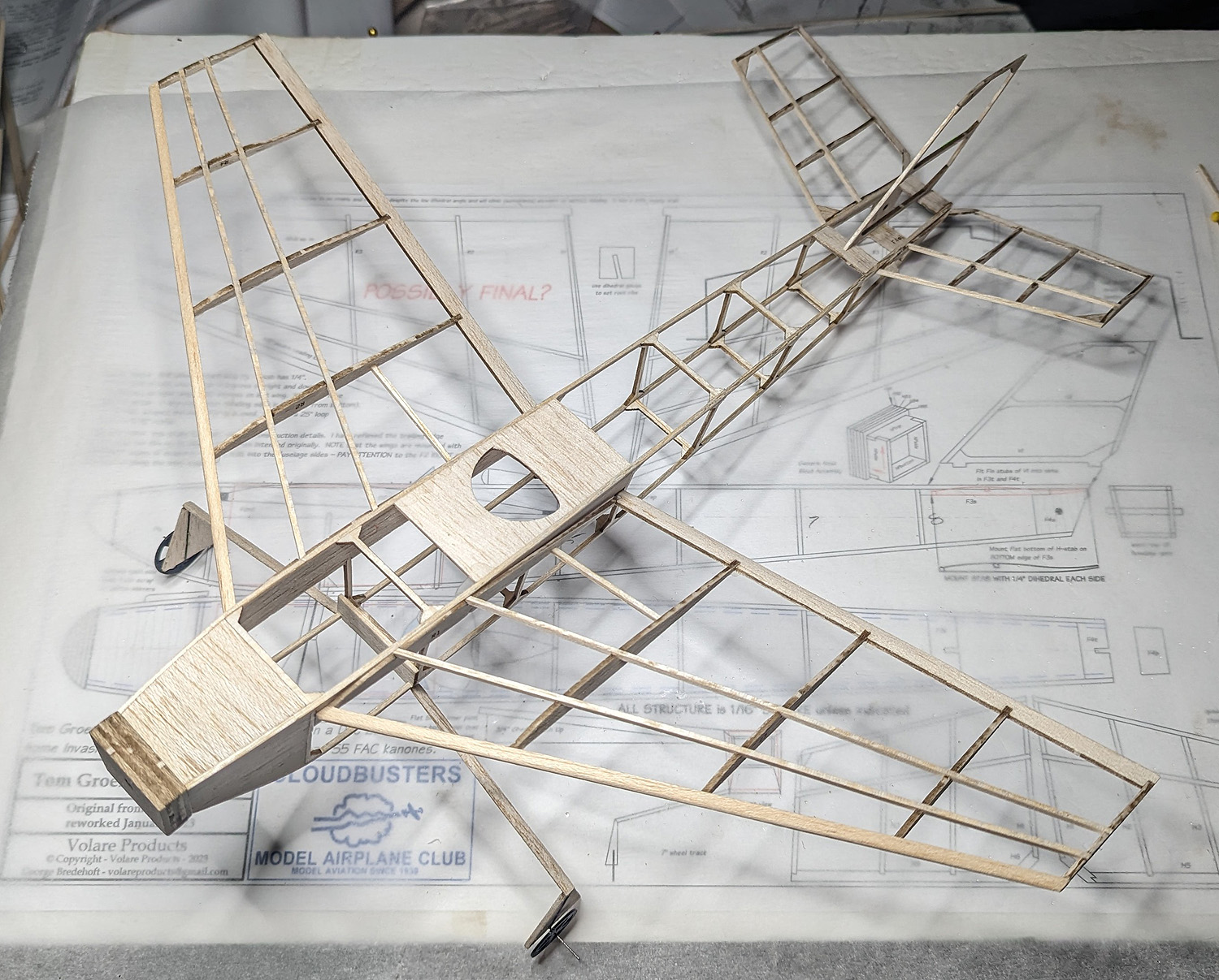
Here is a photo of the fuselage with a note from the plan.

the front view showing the trapezoidal shape of the fuselage. This taper is consistent from nose-to-tail
TAIL ASSEMBLY
Looking at the tail, there are a couple more strange things to be aware of.
1) – you can see the trapezoidal shape is carried through to the rear.
2) – the motor peg is at the very back of the model. This will be a little tricky when mounting in a stooge, because the tube is under the tail plane. But, on the plus-side, the rear of the fuselage is open; this will help when installing a motor.
3) – the horizontal tail is built in two separate pieces and mounted to the sides of the fuselage – with dihedral. I have given you instructions one where to mount and how to align. Again, sand in a little dihedral and carefully glue them in place.
Here’s a photo with notes.
 WING BUILD
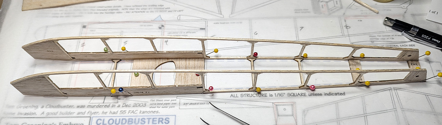
The wing ribs have an unusual shape. The airfoil is the typical “old school” flat bottom with something like a Simplex top arc and a square, butt-jointed Leading Edge. I typically change these to Clark-Y-style airfoils with fish-mouth Leading Edge notches, but I left this one as designed. The original hand-drawing showed that the tip rib (R5) had a reflex in the upper surface. I interpolated this reflex across Ribs 3 and 4, also. This means when covering, the top of the wing will have a gradual bit of concavity between R3 and R5. And then I sanded a small amount of washout on the bottom side of the Trailing Edge between R4 and R5. See photo.
 HORIZONTAL STAB
In addition to the dihedral previously mentioned in the H-stab, these airfoils are reflexed. It wasn’t easy to draw these so they would be well-represented when laser-cut and what I have presented is likely a bit more reflex than Tom originally intended. Who knows (right now I haven’t flown the model*) how this will affect the flight characteristics. Regardless, it does present some construction challenges. I pinned down the LE and installed the ribs and then the spar. This left the TE of the ribs hanging in space. I then made sure the tips were in line and glued the TE piece across all the ribs – still hanging in space. It worked and wasn’t quite as tricky as it sounds. Just be careful and you’ll be fine. Again, see photo.
* – Flight update: this stab, with all the reflex, might be adding up elevator. I had to add about 1g of clay to the nose and it still seems to stall in the glide. I have added a note to the plan that a stab built simply from 1/16″ square sticks might be a better option.
 WING INSTALLATION
One of the most unusual aspects of this build it Tom’s wing incidence angles – THEY ARE DIFFERENT! The Left wing has more incidence than the Right. I can only assume he is trying to counteract torque. Remember – I saw this model fly and it did ok. I don’t remember specifics, but it got up and out and flew. I have built in the differences into the fuselage sides, so the next guy doesn’t need to worry about how to do it. Just leave stubs on the LE and TE and insert them into the fuselage sides. The only thing you have to worry about is putting the wing mount pieces on the correct side of the fuselage! I have etched the proper side designation onto each piece. On mine, I made sure that this text would be outward when the model was assembled. This insured the wings would be mounted per Tom’s design.
Flight update: I tried to fly this model right under power. This did not work very well. It would go right, but as power came off it seemed to spiral in to the right. I “think” the wing orientation is causing this. When I chose to allow it to fly left, I think this is where the wing Angles of Attack really work. The model would climb out to the left with the wings fairly level but gaining a lot of altitude. The glide still needs work, but that will have to wait for a space larger than my back yard.

the front view (barely) shows the different incidence of each wing. the bottom two shots show the LEFT and RIGHT wing mount pieces in their proper locations.
TEST FLIGHT VIDEO
Here are some more build photos.

Winn Moore’s prototype