I am finishing up the build of my second Wanderer. No pictures – I’ve been too busy – except here is a shot of the prop assembly.
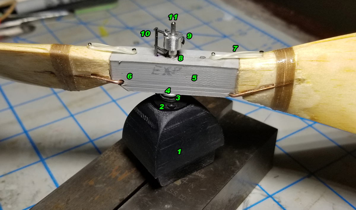
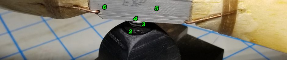
This is “experimental” because of a couple of parts made from non-traditional materials. I made the noseblock and prop hub from 3D printed plastic. “Why?” you might ask. Well, to see if it could be done, mostly. Below are the details called out in the photo. Note that items #1 and #5 are the 3D printed parts. The other items are just explaining what you see.
- Nose Block – Of course, I used the dimensions from my construction drawing to create this. It is mostly hollow, with wall thicknesses of 1/16″. The tip of the nose has a recessed area to receive the front half of a Gizmo Geezer nose button. It seems to be very durable, which was one issue I had with the nose block on my first Wanderer – poor launches and had dives into the ground crushed the soft wood. This shouldn’t crush. However, we all need to remember that if you make the part (any part) strong enough not to break, you are just transferring that energy somewhere else. Also, this has been sanded (mostly) smooth.
- Gizmo Geezer Nose Button – Again, this is the front half of the nose button. The back half, the tri-lobed portion with the three small screw holes is omitted and the holes replicated in the printed nose block. The three Gizmo Geezer adjustment screws screw directly into the nose block.
- Superior Props Thrust Bearing – a traditional ball bearing thrust bearing to absorb the load and make rotation smoother and less friction-filled.
- Superior Props 3/32″ Nose Bearing – So, when I printed the Prop Hub (#5) I printed it with a 3/32″ hole in it (just like we pre-drill the wooden prop hubs). I press-fit a 3/32″ aluminum tubing which is just the right internal diameter to accept the 1/16″ prop shaft. Then, as I often do, I realized that I needed a tube-in-tube to allow the prop to freewheel without the friction generated by the tension of the rubber. I could have just drilled out the plastic slightly to allow the plastic hub to rotate on the 3/32″ aluminum tubing, but I chose to go a different way.I drilled out the hub’s center hole to allow for the insertion of the 3/32″ (Internal Diameter) Nose Button and press fit it into the hub. I used thin CA to secure the aluminum to the plastic. Due to the nature of 3D printing, this disrupted the integrity of the hub – the settings I used in 3D printing allowed for a thin outer wall (about 1/32″ thick) and a 10% cross-hatch fill in all other areas that are not an edge (think of a honeycomb as the interior of that plastic block). So when I drilled the center hole out, I removed the entire wall of the center hole. Using this aluminum hub, I am trying to put some structural integrity back into the part. I couldn’t really print another hub, because the blades were attached long before they were finished and replacing the hub would certainly damage the blades.
- Experimental Prop Hub – I made this to see if it would be possible to address some of the issues we have with our current hub/hinge made of wood and aluminum. (At least, I feel there are issues.) When we make folders, we glue blades to a hub, then install a hinge with wires, bond it to the blades, and cut the blades off the hub. The issue I have with all of this – and maybe some of you have seen this – is that the aluminum hinge can get twisted. This creates two problems: a) the blades do not lay back uniformly and b) when this happens, the pitch of the blade can change.I designed this hub with the holes for the wires integrated into the hub. They cannot move or twist like the aluminum hinges. It took a bit of experimenting to get the holes properly located, but I think they are right. As mentioned above, I have already encountered some things that need to change IF we choose to replace the wood/aluminum hub with this plastic one. I will fly this prop and see how durable the hub is. At the current print density, it is no heavier than the wood prop, so we aren’t sacrificing weight – durability is the test for this flying season.
- Folder Blades – Here you can see the hinge wire, where it enters and exits the hub, and how it is bound to the blade. This is typical of our current hinges, but, as stated above, the hinge is now integrated into the hub, rather than being a separate piece that requires binding and bonding to the hub.
- Dental Band and Pins – these are required for Flying Aces Club rules. The FAC does not permit props that fold prior to landing, so folders must be help open during flight. You might ask “so why put a folder on an FAC plane?” – well, a folder will flex on landing, absorbing that shock of landing. Remember above where I said the nose block was strong and we transfer that energy to other parts of the plane? Here we are trying to absorb that energy of landing and hoping to prevent a) breaking of the prop on landing and b) breaking of the fuselage nose when the nose block pops out. This works well, trust me.
- Tube-in-Tube – You can barely see the 3/32″ internal aluminum tube. You can just see a little bit sticking up above the hub. THIS IS CRITICAL. If you make the internal tube the same length as the external tube (in this case the external tube is the #4 aluminum nose bearing), the prop will not be able to freewheel without binding, due to the tension of the rubber (braided motor) pulling back on the prop shaft. This pull will pull the clutch back on the internal and external tubes equally and prevent free rotation. By making the internal tube longer than the external, all of that binding and tension applies to the internal tube only and the external tube (and prop) are free to spin. I often forget this and wonder why my prop locks in glide.
- Superior Props Freewheel Clutch – This clutch its in front of the prop and firmly attached to the prop shaft. In the position shown here, the bail (wires coming out if the side of the aluminum clutch) are engaged in #10, the drive pin. This is a fairly positive clutch as centrifugal force spins the bail out when the rubber motor is driving the prop. when the power is off, the shaft stops spinning and the clutch stands still. The prop freewheels and when the drive pin comes around, it hits the back of the bail and flips it forward. The legs of the bail are long enough to engage the pin under power, but short enough to clear the pin when folded against the clutch. A notch needs to be ground int eh prop shaft to accept the set screw or the force of the wound motor could pull the shaft out of the clutch if you just rely on the friction of the screw on the shaft.
- Drive Pin – this is part of the clutch and it is a pin embedded in the prop. This pin is 0.039″ wire. I used 0.032″ (1/32″) wire on my first Wanderer and the pin bent. I think that 0.032″ wire was just too weak for the forces applied during full winds, so I went up to the next size of wire. It is possible that I should have gone up to 0.047″, but we will see. Given the internal structure of the plastic hub (mentioned above in #4), I chose to drill all the way through the hub and the drive pin wire has a short “L” bent into the back side. This “L” is positioned right up against the flange of the #4 Nose Bearing and CA’d firmly. This should be strong enough.
- Prop Shaft – This is just a typical 1/16″ music wire prop shaft. Nothing special here, other than I choose 1/16″ because I am 100% positive that 0.047″ would be too weak for this size of plane. I used 1/16″ on my first Wanderer and did have a couple of bad landings where the shaft bent slightly.
This entire assembly is not light. It weighs 18.7 grams as shown. This plastic nose block weighs 5 grams and the finished prop before all of the hubs, bearings, pins, etc was 10.4 grams. So all of the accessories (aluminum, tube, nose bearing, thrust bearing, clutch, drive pin, pins, dental bands, and prop shaft) add the additional 3.5 grams. The same assembly on Wanderer #1 weighs 16.6 grams. Most of the difference is certainly in the plastic nose block. This 2-gram difference in not objectionable to me (yet) and maybe I can move the wing forward a little and make better use of the longer tail moment. That is yet to be seen.